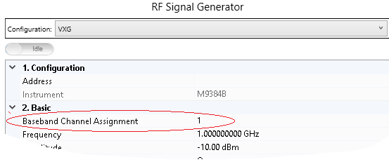
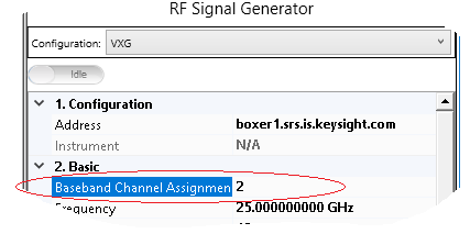
Choose a baseband channel assignment:
Connect RF Out 1 on the front panel of the M9384B VXG to the RF input port of the signal analyzer
Connect 10 MHz Ref Out on the real panel of the M9384B VXG to Ext REF IN of the signal analyzer
Connect CH1 SYNC OUT on the real panel of the M9384B VXG to TRIGGER1 IN of the signal analyzer
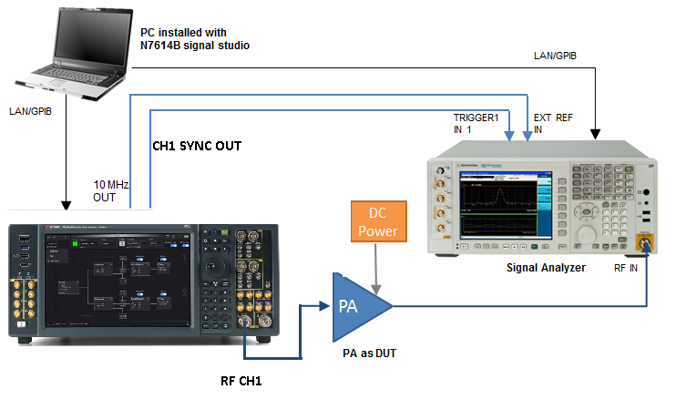
In the system connection diagram above, the dark blue lines are for RF connection; the light blue lines are for reference and trigger signal connection; the black lines are for instrument control connection with LAN or GPIB.
Connect RF Out 2 on the front panel of the M9384B VXG to the RF input port of the signal analyzer
Connect 10 MHz Ref Out on the real panel of the M9384B VXG to Ext REF IN of the signal analyzer
Connect CH2 SYNC OUT on the real panel of the M9384B VXG to TRIGGER1 IN of the signal analyzer
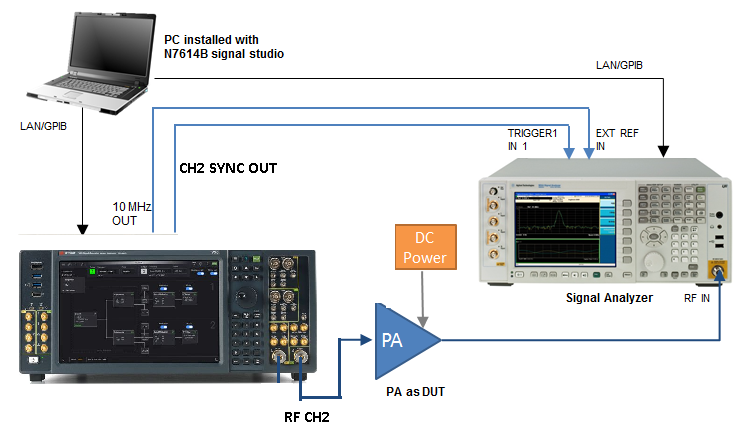
In the system connection diagram above, the dark blue lines are for RF connection; the light blue lines are for reference and trigger signal connection; the black lines are for instrument control connection with LAN or GPIB.